This post by Jeff (@jeffmakes) was delayed due to interferences with other projects but nevertheless, enjoy!
This year, it was my great honour to design the hardware for the Troopers19 badge.
We wanted to make a wifi-connected MicroPython-powered badge; something that would be fun to take home and hack on. It was a nice opportunity to use a microcontroller platform that I hadn’t tried before. I also used the project as a chance to finally migrate my PCB workflow from Eagle to Kicad. Inevitably it was a painful transition, which resulted in quite some delay to the project as I floundered around in the new tool, but it does mean the design files are in an open format which I hope will benefit the community of Troopers attendees and future badge designers!
![]()
Hardware overview
Microcontroller
We decided upon ESP32, as it features wifi and MicroPython support. To provide plenty of IO, memory and space for apps, we selected the ESP32-WROVER module, which features 4MB of flash and 8MB of RAM. It also includes a PCB F-antenna, and the various passives and crystals required to run the ESP32.
Be very careful with your pin assignments when using the WROVER modules. They break out various pins that can’t actually be used, including the SPI pins which are used for communication between the micro and the flash and RAM. I screwed this up several times despite reading the documentation reasonably carefully!
USB
The ESP32 includes a serial bootloader in ROM, but no USB support, so we added a CP2102 USB-serial chip. That allows us to flash a fresh badge over USB with no special hardware. The badge also charges over USB (USB-C for extra coolness). The USB-C cable also functions as the lanyard. We had the cables custom made to the perfect 750mm length!
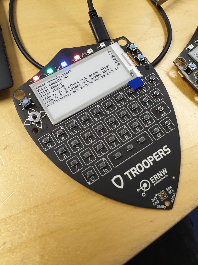
Display
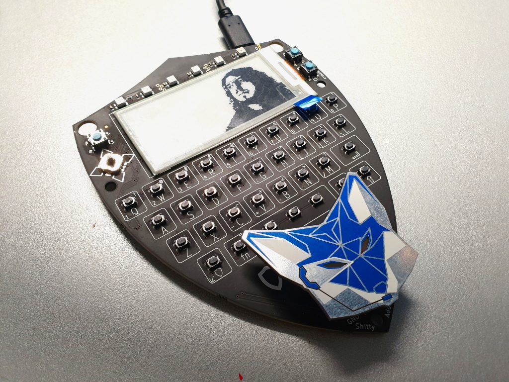
For a nice, flashy appearance, we selected a 2.9″ 296×128 e-paper display from Good Display (GDEH029A1). It supports partial redraw, so we don’t have to erase the whole display to change a small region. This makes the menu interface acceptably quick to use, and makes it possible to delete whilst typing. E-paper displays only use power to draw an image, so the badge has a very long battery life. They continue to display an image for years when powered off.
Keyboard and UI
Since MicroPython provides a pretty much general-purpose OS, we thought it would be fun to make the badge into a general-purpose computer, so we added a full qwerty keyboard! We tested around ten different switch options, and selected one with a nice click and low actuation force. Since the ESP32 doesn’t have anywhere near enough pins for that many switches, we used PCA9555 and PCA9539 I2C IO expanders to connect the switches and joystick to the ESP32. They have interrupt lines so we don’t have to keep polling the bus.
LED’s
We have a row of six WS2812B-mini addressable LED’s on the top edge of the board. They provide us with dimming and colour mixing without taking up timer modules and pins on the micro. Make sure you bake your LED’s if they don’t come in a vacuum-sealed pack. They slowly absorb water from the air, which causes invisible internal fracturing as it boils during soldering. Our assembler soldered a bunch of panels without baking the LED’s, which led to a long debugging effort and a lot of rework!
Accelerometer
We added a LIS3DHTR 3-axis accelerometer, which features variable range selection and motion and tap detection. This is used for the Magic 8 Ball the fitness tracker app :D.
Design Materials
The schematic, layout, gerbers and assembly data are here. To open them you need Kicad version 5 or above.
Shitty Addons
#badgelife has become so big that badges now wear their own badges, or, “Shity Addons”. The Shitty Addon interface comprises 3.3V power and I2C.
Jann Foehringer and I designed the Fuccs Addon. I created the PCB layout using the excellent svg2shenzhen Inkscape extension, which spits out a Kicad module. I can’t stress enough just how great this tool is – every other DXF/SVG import route in every PCB tool I’ve ever used has totally sucked, dropping/corrupting some random set of graphics elements, but this tool Just Works(TM).
The Fuccs Shitty Addon PCB design is up here.
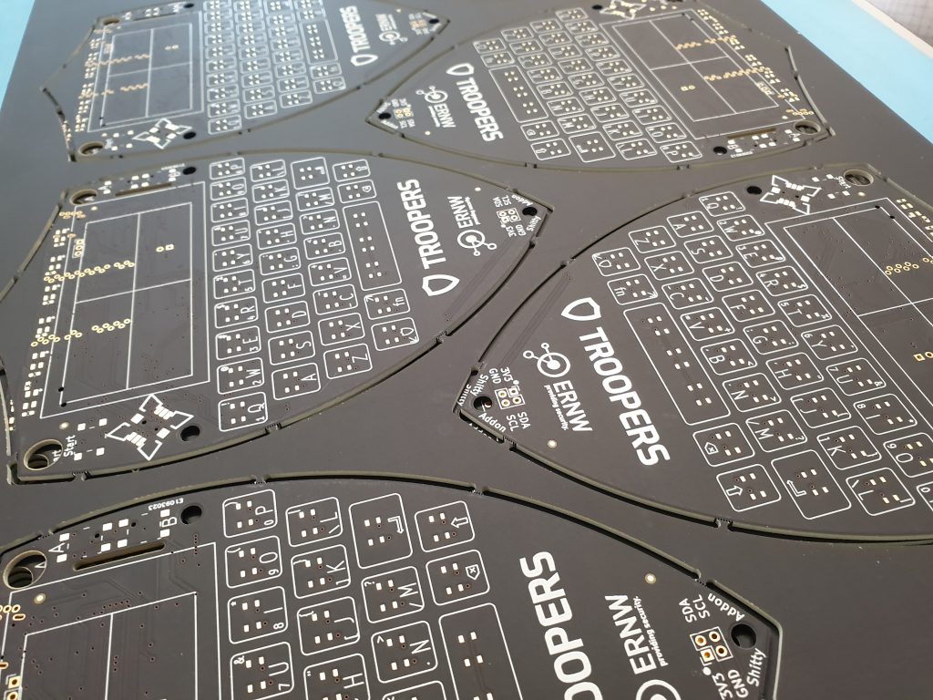
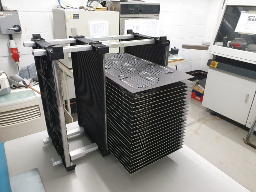
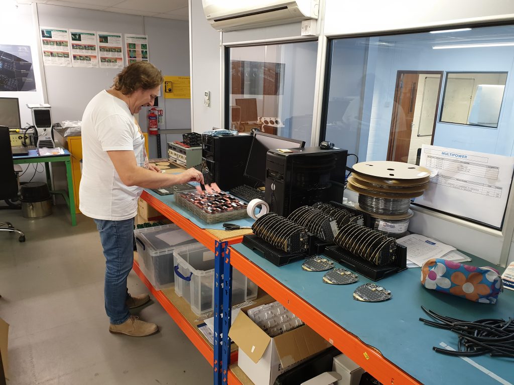
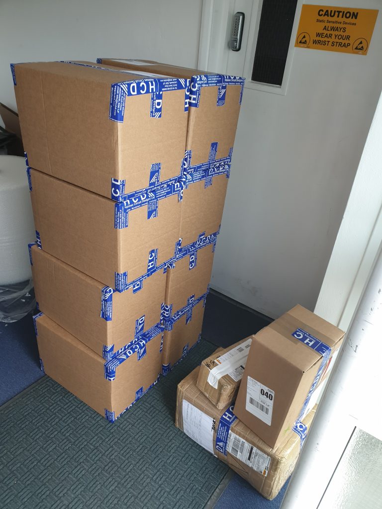
Production
We had the PCB’s fabricated in Hungary, and assembled in the UK. Chinese New Year made matters rather difficult – because production stops in China, all the European manufacturing capacity completely fills up!
Photos:
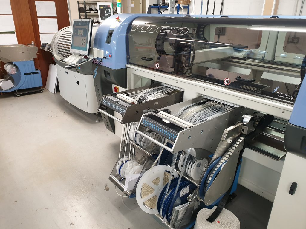
Video:
Have a look at the mesmerising pick-and-place machine assembling a panel.