At times with many many digitally transmittable diseases, protection might be more important than ever. When connecting your smartphone to a rogue charger, or a foreign smartphone to your own laptop, you never now what will happen. You never know what data crosses the lines. But there is help: A USB condom!
As the Troopers 16 Badge was a neat integrated device, we had the challenge to identify something to be soldered for our attendees. The past has shown, that soldering rocks and all of our attendees, all of you, really enjoy it! After some looking around and roaming the Internet, we decided to go for a simple device, which would protect you and your devices in a hostile world. A slim PCB, which will protect your phone when having to connect it to some unknown charger or for situations when “a mate” just wants to connect his/her phone to your laptop for “charging purposes”.
Sadly, the device is not quite as slim as it could be, but why? And how does it actually work?

The Function
As most of you will know basic USB works with four lines: VBus, Ground, Data+, Data-.
While Data+ and Data- will transfer the actual data, VBus and Ground are all you need to charge or power a device. Now the one thing that all USB condoms out there have in common, is the fact that they will disconnect the data lines between the host and the client device. Depending on the scenario the host device may be a laptop, a wall-socket USB charger or one of those magic charging stations at the airport.

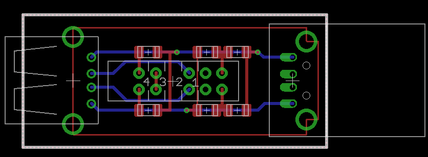
This picture shows the actual layout of the PCB we distributed during Troopers 16. The red layer is the top layer, blue the bottom. On the left is the USB socket, on the right is the plug. In the middle you can see the footprint of the switch.
When having a close look, you can see that the data lines (the two pins in the middle) on the plug’s side are not connected to anything. Neither a red nor a blue line are connected. Due to this fact, there is no way for data traffic to pass through the condom. If you want to verify this, you can use a continuity tester and check for a connection between the data pins on both the socket and the plug.
Basically, if you wanted to, you could just cut open a USB cable, disconnect the data lines and you’d be done. But… 🙂
What’s the Switch For?
As especially Apple users might be familiar with, some phones are very fussy when it comes to charging units. Although the phone might always charge, sometimes that happens really really slow. One reason for this might be the available charging current. A plain USB port on a laptop will offer a current of 0.5 Ampere. When considereing the 5 Volts of a USB port, this results in an electric power of 2.5 Watts. A modern charging unit will offer between 1 Ampere and 2 Ampere, so between 5W and 10W. Some cheap chargers only offer something like 0.2A and, with 1W only, will barely stop the phone’s battery from discharging. Looking at these numbers it makes sense that a phone takes longer to charge on a laptop than on a proper charging unit and even longer on a cheap one.
One should also keep in mind that smartphones are actually able to read certain information from a simple charger. When USB data is transmitted on the D+ or D- lines, it forms a wave. This wave usually oscillates around 0V or Ground. Both the host and client device will apply certain thresholds and grab the data of these lines. On the other hand, when connected to chargers, the D+ and D- lines are set to a certain static voltage. Instead of actively transmitting data, a set of passive resistors is sufficient. So when the phone is connected to a power source, it will measure the voltages on either the D+ or D- or both lines. If the voltage is within a predefined range, the phone will expect the charger to be an “official”/original charging unit.
As with a USB condom both data lines are not connected to the host device, the only information on the charging unit (the voltage on the D+ and D- lines) is lost. Hence most condoms nowadays spoof an original charging unit!
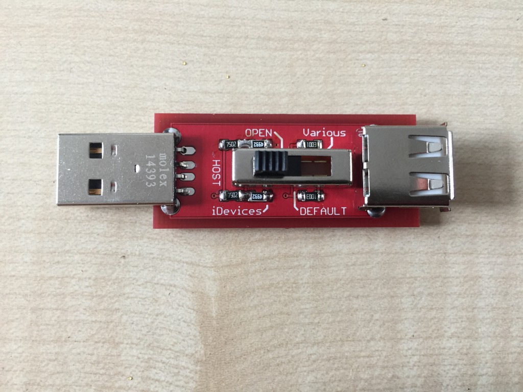
Different devices expect different voltages on the data lines. So a particular condom circuit will only allow charging for a certain set of devices. The switch gives us a little bit of flexibility with the following settings:
- Various: 100k pull-up resistors on both D+ and D-.
- Default: Short between D+ and D-. No resistors applied.
- Open: Nothing connect. D+ and D- are simply not connected to anything.
- iDevices: 49.9k pull-down and 75k pull-up resistors on both D+ and D-.
When using the USB condom with a specific device, you might just need to give all the settings a try and see which one works best!
Soldering and Bill of Materials
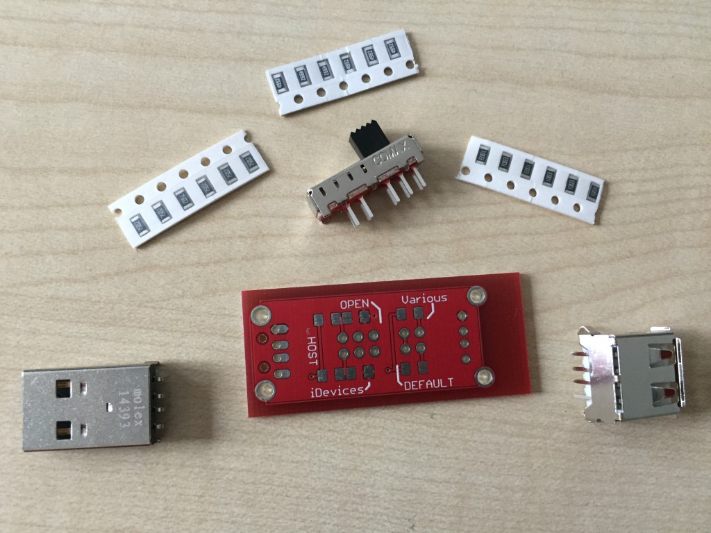
The following parts are necessary for our USB condom
- PCB
- 2 x 100k resistor in SMD – 1206 format
- 2 x 49.9k resistor in SMD – 1206 format
- 2 x 75k resistor in SMD – 1206 format
- 1 x USB A socket
- 1 x USB A plug
- 1 x stereo selector switch

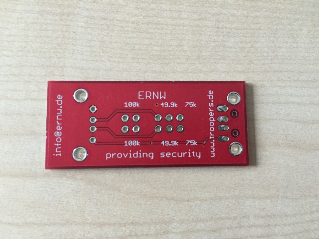
All parts should be placed on the top of the PCB. The exact position of the resistors can be seen on the bottom side of the PCB.
The easiest approach when soldering is to first solder the SMD resistors. Then go for the USB socket and plug and leave the switch till the end. Working in this order makes sure, that the PCB will lie firmly on the table at all times, at least until you add the switch.
If the 49.9k and the 75k resistors are soldered together in the middle, there is no reason to worry, as these are connected anyways.
Modifications
It might also be possible that not a single one of the available settings will really make you happy. If this is the case, you might have to identify a different configuration and solder on a few of your own resistors. You could also drop the switch and simply hardwire the condom to your favorite setting!
As you will want to connect the USB condom to your laptop or your smartphone you should always double check your soldering and verify everything using a multimeter, just to make sure that you did accidentally create a short anywhere.

Happy protected loading!
For the Sorcerers of the Badge,
Brian
The BadgeWizard